Subscribe to historic house plans at www.patreon.com/houseplans.
Villa in the Gothic Style, 1845.
Part II: Chamber Floor, Back Elevation, Details and Plan of Roof.
|
Subscribe to historic house plans at www.patreon.com/houseplans.
Villa in the Gothic Style, 1845.
Part II: Chamber Floor, Back Elevation, Details and Plan of Roof.
|
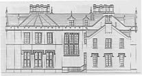
BACK ELEVATION.- The whole extent of the Back Elevation is 89 feet 6 inches. The wing to the left is 32 feet 6 inches wide, and 32 feet 9 inches high from the ground to the top of the battlements, and 41 feet 4 inches high to the ridge of the roof. The windows on the ground floor are 10 feet 3 inches high, by 4 feet 9 inches wide, each being divided into four compartments by a mullion and transom, 5½ inches thick. The top of each window is crowned with a tablet, which reaches 2 feet below the top of the window. The windows on the chamber floor are 20 feet 9 inches from the ground, their height is 7 feet, and width 4 feet. The wing to the right is 30 feet 2 inches wide, and 34 feet 6 inches high from the ground to the gable top; and to the top of the chimney stalk 40 feet 2 inches, to the top of the side walls 25 feet 3 inches, and to the ridge of the roofs over the windows to the right hand 28 feet 4 inches, and to the left 30 feet. The windows on the ground floor are 7 feet 10 inches high, the one in the centre is 3 feet 9 inches wide, the other two are blank windows, each 2 feet 4 inches wide. The top of each window is crowned with a tablet, which reaches 1 feet 9 inches below the top of the window. The windows on the chamber floor are 17 feet 6 inches from the ground, their height is 6 feet, and the width of the one in the centre is 3 feet 6 inches, the other two being 2 feet 2 inches; these windows are blank. The gable top, which stands behind the wing to the right, is 26 feet 9 inches wide, and 41 feet 4 inches high to the top of the roof, and 47 feet 3 inches high from the ground to the top of the chimney stalks. The recesses, terminating at the top with Gothic heads, are 3 feet high, by 6 inches wide. The central compartment or staircase is 13 feet 9 inches from the level of the ground, its height is 14 feet 9 inches, width 9 feet 6 inches, divided into six compartments by two mullions, 11 inches thick, anbd transoms 5½ inches thick. The dormer window over the staircase is 4 feet high, by 3 feet 2 inches wide, its roof being 6 feet 3 inches above the top of the battlements. The dormer window, on the wing to the left, is of the same dimensions. The window on the ground floor between the staircase and wing to the right, is 8 feet 9 inches high, by 2 feet 4 inches wide. The one on the chamber floor is 20 feet 9 inches from the ground; height 7 feet, width 2 feet 2 inches. The dormer window, over this window, is 4 feet high, by 2 feet 2 inches wide, and 6 feet from the top of the battlements to the ridge of its roof. The dormer window on the wing to the right, is of the same size. The turrets on the external angles are the same as those described on the Front Elevation.
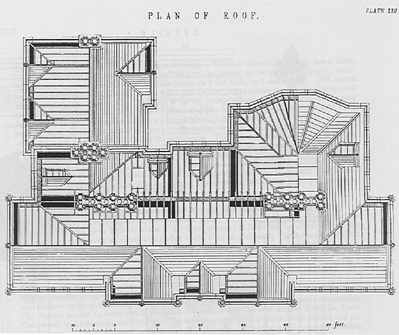
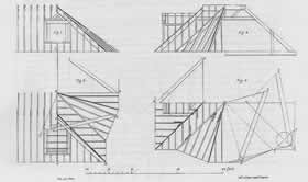
Figure 2, represents the plan of the octagonal part of the roof, showing the method of finding the length of the different rafters, and likewise the different bevels. A, B, and C, on the Plan, show the rafters on the central part of the octagon; the line A, B, being equal to the perpendicular height from the ridge of the roof to the seat of the rafter, and B, C, equal to the distance from the bottom of the perpendicular line to the extremity of the seat on the wall plate, join A, C; and the line thus joined, is the length from the ridge of the roof to the wall plate. The lines drawn perpendicular from the seat of the jack rafters, on the hips, give the length of the different rafters required, and also the bevels at top and bottom for cutting the joints. B D E, on the Plan, show the rafters on the diagonal sides of the octagon; the line B D being equal to the perpendicular height of the roof, and B E equal to the distance from the bottom of the perpendicular line to the extremity of the seat on the wall plate; join D E, which gives the length from the ridge to the wall plate. The lines drawn perpendicular from the seat of the jack rafters on the hip and valley rafter, give the different lengths required, and also the bevels at top and bottom for cutting the joints. F G H, on the Plan, show the rafters on the square part of the roof, the line F G being equal to the perpendicular height of the roof; G H, equal to the distance from the bottom of the perpendicular line to the extremity of the seat on the wall plate, join F H, which gives the length of the rafters on the square part of the roof; the length of the jack rafters is found by perpendicular lines drawn from the seat on the hip and valley rafter, and also the different bevels required for cutting the joints.
Figure 3, represents the elevation of one half of the octagonal part of the roof, the other half of the drawing shows the form of the couples on the square part of the roof, and also a side view of the framing of the dormer window.
Figure 4, represents the plan of the octagonal part of the roof, and shows the method of finding the lengths of the hip and valley rafters, also the various bevels, and backing of the hips. A B C, on the Plan, shows one of the rafters on the square part of the roof, with the seat of the sill and lintel of the dormer window marked by dotted lines. D E F, on the Plan, shows the method of finding the length of the hip rafters on the octagonal part of the roof, draw D E perpendicular to D F, make D E equal to the height of the roof, join E F, which gives the length of the hip required. G H I is the hip rafter on the square part of the roof, the length of it is found by the same rule as the former. To find the backing of the hips.-From any point in I G, draw a b perpendicular to I G, cutting the line at the extremity of the seats of the bottom of the rafters in a c and b c, then a b c will be the angle required. The backing of the hip rafter E F is shown on the drawing in the same manner. The method of finding the side bevels on the different rafters, is shown on the drawing by bevels applied to the various joints.
|
| House Plans | Samples | Privacy Policy | Home |